Collection of validation models
Information
This package contains validation models for the classes in
Annex60.Fluid.Movers.
Note that most validation models contain simple input data
which may not be realistic, but for which the correct
output can be obtained through an analytic solution.
The examples plot various outputs, which have been verified against these
solutions. These model outputs are stored as reference data and
used for continuous validation whenever models in the library change.
Extends from Modelica.Icons.ExamplesPackage (Icon for packages containing runnable examples).
Package Content
| Name |
Description |
 ControlledFlowMachine ControlledFlowMachine
|
Fans with different control signals as input |
| ControlledFlowMachineDynamic
|
Fans with different control signals as input and a dynamic speed signal |
| FlowControlled_dp
|
Fan with zero mass flow rate and head as input |
| FlowControlled_m_flow
|
Fan with zero mass flow rate and mass flow rate as input |
| PowerExact
|
Power calculation comparison among three mover types, using exact power computation for m_flow and dp |
| PowerSimplified
|
Power calculation comparison among three mover types, using simplified power computation for m_flow and dp |
 PumpCurveConstruction PumpCurveConstruction
|
Validation model that tests that the pump curve is properly extrapolated to V=0 and dp=0 |
 PumpCurveDerivatives PumpCurveDerivatives
|
Check for monotoneously increasing pump curve relations between Nrpm, dp and m_flow |
| Pump_Nrpm_stratos
|
Model validation using a Wilo Stratos 80/1-12 pump |
| Pump_stratos
|
Stratos pumps with speed as input |
| SpeedControlled_Nrpm
|
Fan with zero mass flow rate and speed as input |
| SpeedControlled_y
|
Fan with zero mass flow rate and control signal y as input |
| SpeedControlled_y_linear
|
Pump with linear characteristic for pressure vs. flow rate |
 BaseClasses BaseClasses
|
Package with base classes for Annex60.Fluid.Movers.Validation |
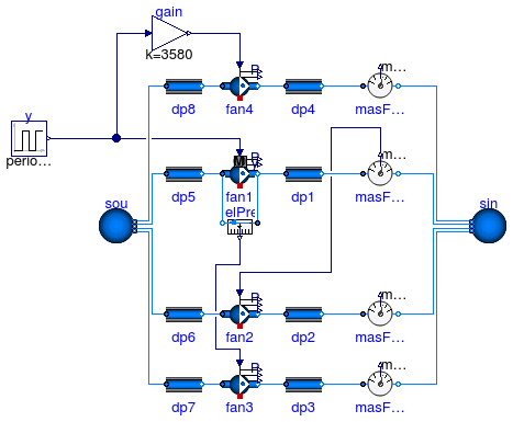
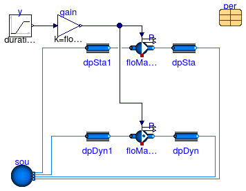
Fans with different control signals as input
Information
This example demonstrates the use of the flow model with four different configurations.
At steady-state, all flow models have the same mass flow rate and pressure difference.
Note that addPowerToMedium=false since otherwise,
Dymola computes the enthalpy change of the component as a fraction (k*m_flow+P_internal)/m_flow
which leads to an error because of 0/0 at zero flow rate.
Extends from Modelica.Icons.Example (Icon for runnable examples), Annex60.Fluid.Movers.Validation.BaseClasses.ControlledFlowMachine.
Modelica definition
model ControlledFlowMachine
extends Modelica.Icons.Example;
extends Annex60.Fluid.Movers.Validation.BaseClasses.ControlledFlowMachine(
fan4(addPowerToMedium=false, filteredSpeed=false,
energyDynamics=Modelica.Fluid.Types.Dynamics.FixedInitial),
fan1(addPowerToMedium=false,
energyDynamics=Modelica.Fluid.Types.Dynamics.FixedInitial),
fan2(addPowerToMedium=false, filteredSpeed=false,
energyDynamics=Modelica.Fluid.Types.Dynamics.FixedInitial),
fan3(addPowerToMedium=false, filteredSpeed=false,
energyDynamics=Modelica.Fluid.Types.Dynamics.FixedInitial));
end ControlledFlowMachine;
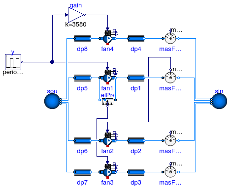
Fans with different control signals as input and a dynamic speed signal
Information
This example demonstrates the use of the flow model with four different configurations.
At steady-state, all flow models have the same mass flow rate and pressure difference.
Extends from Modelica.Icons.Example (Icon for runnable examples), Annex60.Fluid.Movers.Validation.BaseClasses.ControlledFlowMachine.
Modelica definition
model ControlledFlowMachineDynamic
extends Modelica.Icons.Example;
extends Annex60.Fluid.Movers.Validation.BaseClasses.ControlledFlowMachine(
fan4(energyDynamics=Modelica.Fluid.Types.Dynamics.FixedInitial),
fan1(energyDynamics=Modelica.Fluid.Types.Dynamics.FixedInitial),
fan2(energyDynamics=Modelica.Fluid.Types.Dynamics.FixedInitial),
fan3(energyDynamics=Modelica.Fluid.Types.Dynamics.FixedInitial));
end ControlledFlowMachineDynamic;
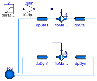
Fan with zero mass flow rate and head as input
Information
This example demonstrates and tests the use of a flow machine whose mass flow rate is reduced to zero.
The fans have been configured as steady-state models.
This ensures that the actual speed is equal to the input signal.
Extends from Modelica.Icons.Example (Icon for runnable examples), Annex60.Fluid.Movers.Validation.BaseClasses.FlowMachine_ZeroFlow (Base class to test flow machines with zero flow rate).
Parameters
| Type | Name | Default | Description |
|---|
| replaceable package Medium | Air | Medium model |
| MassFlowRate | m_flow_nominal | 1 | Nominal mass flow rate [kg/s] |
| PressureDifference | dp_nominal | 500 | Nominal pressure difference [Pa] |
Modelica definition
model FlowControlled_dp
extends Modelica.Icons.Example;
extends Annex60.Fluid.Movers.Validation.BaseClasses.FlowMachine_ZeroFlow(
gain(k=dp_nominal),
redeclare Annex60.Fluid.Movers.FlowControlled_dp floMacSta(
redeclare package Medium =
Medium,
m_flow_nominal=m_flow_nominal,
filteredSpeed=false,
energyDynamics=Modelica.Fluid.Types.Dynamics.SteadyState),
redeclare Annex60.Fluid.Movers.FlowControlled_dp floMacDyn(
redeclare package Medium =
Medium,
m_flow_nominal=m_flow_nominal,
filteredSpeed=false,
energyDynamics=Modelica.Fluid.Types.Dynamics.FixedInitial));
equation
connect(gain.y, floMacSta.dp_in);
connect(gain.y, floMacDyn.dp_in);
end FlowControlled_dp;
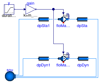
Fan with zero mass flow rate and mass flow rate as input
Information
This example demonstrates and tests the use of a flow machine whose mass flow rate is reduced to zero.
The fans have been configured as steady-state models.
This ensures that the actual speed is equal to the input signal.
Extends from Modelica.Icons.Example (Icon for runnable examples), Annex60.Fluid.Movers.Validation.BaseClasses.FlowMachine_ZeroFlow (Base class to test flow machines with zero flow rate).
Parameters
| Type | Name | Default | Description |
|---|
| replaceable package Medium | Air | Medium model |
| MassFlowRate | m_flow_nominal | 1 | Nominal mass flow rate [kg/s] |
| PressureDifference | dp_nominal | 500 | Nominal pressure difference [Pa] |
Modelica definition
model FlowControlled_m_flow
extends Modelica.Icons.Example;
extends Annex60.Fluid.Movers.Validation.BaseClasses.FlowMachine_ZeroFlow(
gain(k=m_flow_nominal),
redeclare Annex60.Fluid.Movers.FlowControlled_m_flow floMacSta(
redeclare package Medium =
Medium,
m_flow_nominal=m_flow_nominal,
filteredSpeed=false,
energyDynamics=Modelica.Fluid.Types.Dynamics.SteadyState),
redeclare Annex60.Fluid.Movers.FlowControlled_m_flow floMacDyn(
redeclare package Medium =
Medium,
m_flow_nominal=m_flow_nominal,
filteredSpeed=false,
energyDynamics=Modelica.Fluid.Types.Dynamics.FixedInitial));
equation
connect(gain.y, floMacSta.m_flow_in);
connect(gain.y, floMacDyn.m_flow_in);
end FlowControlled_m_flow;
Power calculation comparison among three mover types, using exact power computation for m_flow and dp
Information
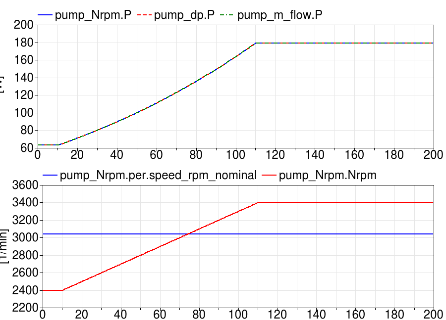
This example is identical to
Annex60.Fluid.Movers.Validation.PowerSimplified, except that the
performance data for the flow controlled pumps
pump_dp and pump_m_flow contain
the pressure curves and efficiency curves.
The plot below shows that this leads to a computation of the power consumption
that is identical to the one from the speed controlled pump pump_Nrpm.
Extends from PowerSimplified (Power calculation comparison among three mover types, using simplified power computation for m_flow and dp).
Parameters
Modelica definition
model PowerExact
extends PowerSimplified(
pump_dp(per=per),
pump_m_flow(per=per));
end PowerExact;
Power calculation comparison among three mover types, using simplified power computation for m_flow and dp
Information
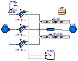
This example compares the power consumed by pumps that
take three different control signals.
Each pump has identical mass flow rate and pressure rise.
Note that for the instances
Annex60.Fluid.Movers.FlowControlled_dp
and
Annex60.Fluid.Movers.FlowControlled_m_flow,
we had to assign the efficiencies (otherwise the default constant
efficiency of 0.7 would have been used).
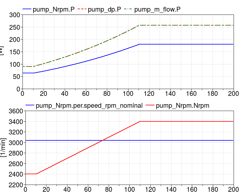
In these models, the power consumption is computed
using similarity laws, but using the mass flow rate as opposed
to the speed, because speed is not known in these two models.
This is an approximation at operating points in which
the speed is different from the nominal speed N_nominal
because similarity laws are valid for speed and not for
mass flow rate.
The figure below shows the approximation error for the
power calculation where the speed Nrpm differs from
the nominal speed Nnominal.
Extends from Modelica.Icons.Example (Icon for runnable examples).
Parameters
Modelica definition
model PowerSimplified
extends Modelica.Icons.Example;
package Medium =
Annex60.Media.Water ;
parameter Modelica.SIunits.MassFlowRate m_flow_nominal=3
;
parameter Data.Pumps.Wilo.Stratos30slash1to8 per ;
Annex60.Fluid.Movers.SpeedControlled_Nrpm pump_Nrpm(
redeclare package Medium = Medium,
per=per,
filteredSpeed=false,
energyDynamics=Modelica.Fluid.Types.Dynamics.SteadyStateInitial)
;
Annex60.Fluid.Movers.FlowControlled_dp pump_dp(
redeclare package Medium = Medium,
redeclare Data.Pumps.Wilo.Stratos30slash1to8 per(
pressure(V_flow={0,0}, dp={0,0}),
use_powerCharacteristic=false,
hydraulicEfficiency(V_flow={0}, eta={0.3577})),
filteredSpeed=false,
m_flow_nominal=m_flow_nominal,
energyDynamics=Modelica.Fluid.Types.Dynamics.SteadyStateInitial)
;
Annex60.Fluid.Movers.FlowControlled_m_flow pump_m_flow(
redeclare package Medium = Medium,
m_flow_nominal=m_flow_nominal,
redeclare Data.Pumps.Wilo.Stratos30slash1to8 per(
pressure(V_flow={0,0}, dp={0,0}),
use_powerCharacteristic=false,
hydraulicEfficiency(V_flow={0}, eta={0.3577})),
filteredSpeed=false,
energyDynamics=Modelica.Fluid.Types.Dynamics.SteadyStateInitial)
;
Annex60.Fluid.Sources.Boundary_pT bou(
nPorts=3,
redeclare package Medium = Medium) ;
Annex60.Fluid.FixedResistances.PressureDrop[3] res(
redeclare each package Medium = Medium,
each m_flow_nominal=m_flow_nominal,
each dp_nominal=40000) ;
Annex60.Fluid.Sources.Boundary_pT sink(
nPorts=3,
redeclare package Medium = Medium);
Modelica.Blocks.Sources.Ramp ramp(
duration=100,
startTime=10,
height=1000,
offset=2400) ;
Modelica.Blocks.Sources.RealExpression dpSet(y=pump_Nrpm.port_b.p - pump_Nrpm.port_a.p)
;
Modelica.Blocks.Sources.RealExpression m_flowSet(y=pump_Nrpm.port_a.m_flow)
;
Modelica.Blocks.Routing.Multiplex3 result;
equation
connect(bou.ports[1], pump_Nrpm.port_a);
connect(pump_dp.port_a, bou.ports[2]);
connect(pump_m_flow.port_a, bou.ports[3]);
connect(pump_Nrpm.port_b, res[1].port_a);
connect(pump_dp.port_b, res[2].port_a);
connect(pump_m_flow.port_b, res[3].port_a);
connect(sink.ports[1:3], res.port_b);
connect(ramp.y, pump_Nrpm.Nrpm);
connect(m_flowSet.y, pump_m_flow.m_flow_in);
connect(result.u1[1], pump_Nrpm.P);
connect(result.u2[1], pump_dp.P);
connect(result.u3[1], pump_m_flow.P);
connect(dpSet.y, pump_dp.dp_in);
end PowerSimplified;
Validation model that tests that the pump curve is properly extrapolated to V=0 and dp=0
Information
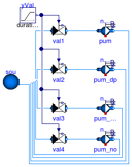
This example tests whether the construction of the pump curve is correct implemented
for the cases where no data point is given at zero head, zero mass flow rate, or both.
Each pump is identical, but different points on the pump curve are specified.
However, the pump curves are linear and hence, because the pump curves are linearly
extrapolated, all four pumps need to give the same flow rate.
Implementation
The pump curves are such that the protected parameter curve
of the pumps have different values. This then tests the correct extrapolation.
Extends from Modelica.Icons.Example (Icon for runnable examples).
Parameters
| Type | Name | Default | Description |
|---|
| MassFlowRate | m_flow_nominal | 1 | Nominal mass flow rate at zero pump head [kg/s] |
| VolumeFlowRate | V_flow_nominal | m_flow_nominal/1000 | Nominal mass flow rate at zero pump head [m3/s] |
| PressureDifference | dp_nominal | 10000 | Nominal pump head at zero mass flow rate [Pa] |
Modelica definition
model PumpCurveConstruction
extends Modelica.Icons.Example;
package Medium =
Annex60.Media.Water ;
parameter Modelica.SIunits.MassFlowRate m_flow_nominal = 1
;
parameter Modelica.SIunits.VolumeFlowRate V_flow_nominal = m_flow_nominal/1000
;
parameter Modelica.SIunits.PressureDifference dp_nominal = 10000
;
Actuators.Valves.TwoWayLinear val1(
redeclare package Medium = Medium,
m_flow_nominal=m_flow_nominal,
filteredOpening=false,
dpValve_nominal=dp_nominal/1000,
from_dp=false) ;
Sources.Boundary_pT sou(
redeclare package Medium = Medium,
use_p_in=false,
nPorts=8,
p=101325,
T=293.15) ;
Annex60.Fluid.Movers.SpeedControlled_y pum(
redeclare package Medium = Medium,
energyDynamics=Modelica.Fluid.Types.Dynamics.SteadyState,
filteredSpeed=false,
per(pressure(
V_flow={0,0.5*V_flow_nominal,V_flow_nominal},
dp={dp_nominal,0.5*dp_nominal,0})),
inputType=Annex60.Fluid.Types.InputType.Constant)
;
Annex60.Fluid.Movers.SpeedControlled_y pum_dp(
redeclare package Medium = Medium,
energyDynamics=Modelica.Fluid.Types.Dynamics.SteadyState,
filteredSpeed=false,
per(pressure(
V_flow={0.5*V_flow_nominal, 0.75*V_flow_nominal, V_flow_nominal},
dp={0.5*dp_nominal, 0.25*dp_nominal, 0})),
inputType=Annex60.Fluid.Types.InputType.Constant)
;
Annex60.Fluid.Movers.SpeedControlled_y pum_m_flow(
redeclare package Medium = Medium,
energyDynamics=Modelica.Fluid.Types.Dynamics.SteadyState,
filteredSpeed=false,
per(pressure(
V_flow={0, 0.25*V_flow_nominal, 0.5*V_flow_nominal},
dp={dp_nominal, 0.75*dp_nominal, 0.5*dp_nominal})),
inputType=Annex60.Fluid.Types.InputType.Constant)
;
Annex60.Fluid.Movers.SpeedControlled_y pum_no(
redeclare package Medium = Medium,
energyDynamics=Modelica.Fluid.Types.Dynamics.SteadyState,
filteredSpeed=false,
per(pressure(
V_flow={0.25*V_flow_nominal,0.5*V_flow_nominal,0.75*V_flow_nominal},
dp={0.75*dp_nominal,0.5*dp_nominal,0.25*dp_nominal})),
inputType=Annex60.Fluid.Types.InputType.Constant)
;
Modelica.Blocks.Sources.Ramp yVal(
duration=1,
offset=1,
height=-0.99) ;
Actuators.Valves.TwoWayLinear val2(
redeclare package Medium = Medium,
m_flow_nominal=m_flow_nominal,
filteredOpening=false,
dpValve_nominal=dp_nominal/1000,
from_dp=false) ;
Actuators.Valves.TwoWayLinear val3(
redeclare package Medium = Medium,
m_flow_nominal=m_flow_nominal,
filteredOpening=false,
dpValve_nominal=dp_nominal/1000,
from_dp=false) ;
Actuators.Valves.TwoWayLinear val4(
redeclare package Medium = Medium,
m_flow_nominal=m_flow_nominal,
filteredOpening=false,
dpValve_nominal=dp_nominal/1000,
from_dp=false) ;
equation
connect(pum.port_a, val1.port_b);
connect(val1.port_a, sou.ports[1]);
connect(yVal.y, val1.y);
connect(pum_dp.port_a, val2.port_b);
connect(pum_m_flow.port_a, val3.port_b);
connect(sou.ports[2], val2.port_a);
connect(val3.port_a, sou.ports[3]);
connect(yVal.y, val2.y);
connect(yVal.y, val3.y);
connect(val4.port_a, sou.ports[4]);
connect(val4.port_b, pum_no.port_a);
connect(yVal.y, val4.y);
connect(pum_no.port_b, sou.ports[5]);
connect(pum_m_flow.port_b, sou.ports[6]);
connect(pum_dp.port_b, sou.ports[7]);
connect(pum.port_b, sou.ports[8]);
end PumpCurveConstruction;
Check for monotoneously increasing pump curve relations between Nrpm, dp and m_flow
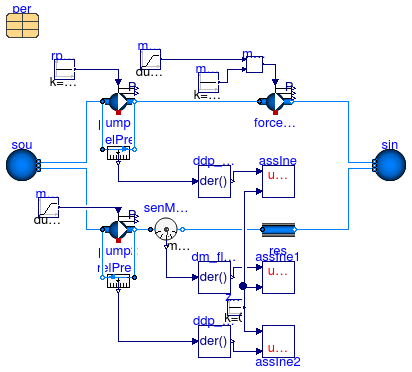
Information
This example checks if the pump similarity law implementation results in
monotoneously increasing or decreasing relations between dp,
m_flow and Nrpm.
Extends from Modelica.Icons.Example (Icon for runnable examples).
Parameters
Modelica definition
model PumpCurveDerivatives
extends Modelica.Icons.Example;
package Medium =
Modelica.Media.Water.ConstantPropertyLiquidWater;
parameter Data.Pumps.Wilo.Stratos80slash1to12 per ;
Annex60.Fluid.Sources.Boundary_pT sou(
redeclare package Medium = Medium,
nPorts=2) ;
Annex60.Fluid.Sources.Boundary_pT sin(
redeclare package Medium =Medium,
nPorts=2) ;
Modelica.Blocks.Sources.Ramp m_flow(
height=60/3.6,
offset=0,
duration=1,
startTime=0) ;
Annex60.Fluid.Movers.SpeedControlled_Nrpm pump1(
y_start=1,
redeclare package Medium = Medium,
energyDynamics=Modelica.Fluid.Types.Dynamics.SteadyState,
per=per,
filteredSpeed=false) ;
Annex60.Fluid.Movers.SpeedControlled_Nrpm pump2(
y_start=1,
redeclare package Medium = Medium,
energyDynamics=Modelica.Fluid.Types.Dynamics.SteadyState,
per=per,
filteredSpeed=false) ;
Annex60.Fluid.Movers.FlowControlled_m_flow forcedPump1(
redeclare package
Medium = Medium, m_flow_nominal=3,
energyDynamics=Modelica.Fluid.Types.Dynamics.SteadyState,
filteredSpeed=false) ;
Modelica.Blocks.Sources.Constant rpm1(k=1000) ;
Modelica.Blocks.Math.Min min1
;
Modelica.Blocks.Sources.Constant mMax_flow(k=40/3.6)
;
FixedResistances.PressureDrop res(
redeclare package Medium = Medium,
m_flow_nominal=40/3.6,
dp_nominal=7e4) ;
Modelica.Blocks.Sources.Ramp m_flow1(
duration=1,
startTime=0,
height=100,
offset=0) ;
Sensors.RelativePressure relPre(
redeclare package Medium =
Medium);
Modelica.Blocks.Continuous.Der ddp_dm_flow
;
Annex60.Utilities.Diagnostics.AssertInequality assIne(threShold=1e-8)
;
Annex60.Fluid.Sensors.RelativePressure relPre1(
redeclare package Medium = Medium);
Modelica.Blocks.Continuous.Der ddp_dNrpm ;
Sensors.MassFlowRate senMasFlo(
redeclare package Medium = Medium)
;
Modelica.Blocks.Continuous.Der dm_flow_dNrpm
;
Annex60.Utilities.Diagnostics.AssertInequality assIne1(threShold=1e-8)
;
Annex60.Utilities.Diagnostics.AssertInequality assIne2(threShold=1e-8)
;
Modelica.Blocks.Sources.Constant zero(k=0) ;
equation
connect(sou.ports[1], pump1.port_a);
connect(forcedPump1.port_a, pump1.port_b);
connect(pump1.Nrpm, rpm1.y);
connect(pump2.port_a, sou.ports[2]);
connect(forcedPump1.m_flow_in, min1.y);
connect(min1.u1, m_flow.y);
connect(mMax_flow.y, min1.u2);
connect(forcedPump1.port_b, sin.ports[1]);
connect(res.port_b, sin.ports[2]);
connect(m_flow1.y, pump2.Nrpm);
connect(ddp_dm_flow.u, relPre.p_rel);
connect(relPre1.port_b, pump2.port_a);
connect(relPre1.port_a, pump2.port_b);
connect(ddp_dNrpm.u, relPre1.p_rel);
connect(senMasFlo.port_a, pump2.port_b);
connect(senMasFlo.port_b, res.port_a);
connect(senMasFlo.m_flow, dm_flow_dNrpm.u);
connect(dm_flow_dNrpm.y, assIne1.u1);
connect(zero.y, assIne1.u2);
connect(ddp_dNrpm.y, assIne2.u1);
connect(assIne2.u2, zero.y);
connect(relPre.port_b, pump1.port_b);
connect(relPre.port_a, pump1.port_a);
connect(ddp_dm_flow.y, assIne.u1);
connect(assIne.u2, zero.y);
end PumpCurveDerivatives;
Model validation using a Wilo Stratos 80/1-12 pump
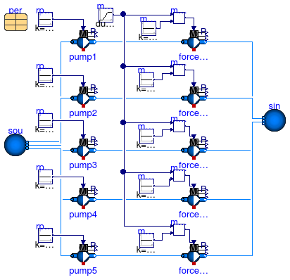
Information
This example provides a validation for the Nrpm model.
A Wilo Stratos 80/1-12 pump is simulated for five different RPMs for load
that changes with time.
The resulting curves for the pump head and mass flow rate are plotted
using colored lines over the pump data sheet.
The resulting figures are shown below.
Pump heads:
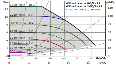
Pump electrical power:
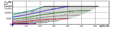
The figures are adapted from the
Wilo Stratos 80/1-12 data sheet.
Extends from Modelica.Icons.Example (Icon for runnable examples).
Parameters
Modelica definition
model Pump_Nrpm_stratos
extends Modelica.Icons.Example;
package Medium =
Modelica.Media.Water.ConstantPropertyLiquidWater;
parameter Data.Pumps.Wilo.Stratos80slash1to12 per ;
Annex60.Fluid.Sources.Boundary_pT sou(
redeclare package Medium = Medium,
nPorts=5) ;
Annex60.Fluid.Sources.Boundary_pT sin(
redeclare package Medium =Medium,
nPorts=5) ;
Modelica.Blocks.Sources.Ramp m_flow(
startTime=100,
duration=800,
height=60/3.6,
offset=0) ;
Annex60.Fluid.Movers.SpeedControlled_Nrpm pump1(
y_start=1,
redeclare package Medium = Medium,
energyDynamics=Modelica.Fluid.Types.Dynamics.SteadyState,
per=per) ;
Annex60.Fluid.Movers.SpeedControlled_Nrpm pump2(
y_start=1,
redeclare package Medium = Medium,
energyDynamics=Modelica.Fluid.Types.Dynamics.SteadyState,
per=per) ;
Annex60.Fluid.Movers.SpeedControlled_Nrpm pump3(
y_start=1,
redeclare package Medium = Medium,
energyDynamics=Modelica.Fluid.Types.Dynamics.SteadyState,
per=per) ;
Annex60.Fluid.Movers.SpeedControlled_Nrpm pump4(
y_start=1,
redeclare package Medium = Medium,
energyDynamics=Modelica.Fluid.Types.Dynamics.SteadyState,
per=per) ;
Annex60.Fluid.Movers.SpeedControlled_Nrpm pump5(
y_start=1,
redeclare package Medium = Medium,
energyDynamics=Modelica.Fluid.Types.Dynamics.SteadyState,
per=per) ;
Annex60.Fluid.Movers.FlowControlled_m_flow forcedPump1(
redeclare package
Medium = Medium, m_flow_nominal=3,
energyDynamics=Modelica.Fluid.Types.Dynamics.SteadyState)
;
Annex60.Fluid.Movers.FlowControlled_m_flow forcedPump2(
redeclare package
Medium = Medium, m_flow_nominal=3,
energyDynamics=Modelica.Fluid.Types.Dynamics.SteadyState)
;
Annex60.Fluid.Movers.FlowControlled_m_flow forcedPump3(
redeclare package
Medium = Medium, m_flow_nominal=3,
energyDynamics=Modelica.Fluid.Types.Dynamics.SteadyState)
;
Annex60.Fluid.Movers.FlowControlled_m_flow forcedPump4(
redeclare package
Medium = Medium, m_flow_nominal=3,
energyDynamics=Modelica.Fluid.Types.Dynamics.SteadyState)
;
Annex60.Fluid.Movers.FlowControlled_m_flow forcedPump5(
redeclare package
Medium = Medium, m_flow_nominal=3,
energyDynamics=Modelica.Fluid.Types.Dynamics.SteadyState)
;
Modelica.Blocks.Sources.Constant rpm1(k=2960) ;
Modelica.Blocks.Sources.Constant rpm2(k=2610) ;
Modelica.Blocks.Sources.Constant rpm3(k=1930) ;
Modelica.Blocks.Sources.Constant rpm4(k=3300) ;
Modelica.Blocks.Sources.Constant rpm5(k=900) ;
Modelica.Blocks.Math.Min min1
;
Modelica.Blocks.Math.Min min2
;
Modelica.Blocks.Math.Min min3
;
Modelica.Blocks.Math.Min min4
;
Modelica.Blocks.Math.Min min5
;
Modelica.Blocks.Sources.Constant mMax_flow1(k=40/3.6)
;
Modelica.Blocks.Sources.Constant mMax_flow2(k=55/3.6)
;
Modelica.Blocks.Sources.Constant mMax_flow3(k=40/3.6)
;
Modelica.Blocks.Sources.Constant mMax_flow4(k=22/3.6)
;
Modelica.Blocks.Sources.Constant mMax_flow5(k=16/3.6)
;
equation
connect(sou.ports[1], pump1.port_a);
connect(forcedPump1.port_a, pump1.port_b);
connect(pump1.Nrpm, rpm1.y);
connect(pump2.port_a, sou.ports[2]);
connect(pump3.port_a, sou.ports[3]);
connect(pump4.port_a, sou.ports[4]);
connect(pump5.port_a, sou.ports[5]);
connect(pump2.port_b, forcedPump2.port_a);
connect(pump3.port_b, forcedPump3.port_a);
connect(pump4.port_b, forcedPump4.port_a);
connect(pump5.port_b, forcedPump5.port_a);
connect(rpm2.y, pump2.Nrpm);
connect(rpm3.y, pump3.Nrpm);
connect(rpm4.y, pump4.Nrpm);
connect(rpm5.y, pump5.Nrpm);
connect(forcedPump1.m_flow_in, min1.y);
connect(min1.u1, m_flow.y);
connect(min2.y, forcedPump2.m_flow_in);
connect(min2.u1, m_flow.y);
connect(min3.y, forcedPump3.m_flow_in);
connect(min5.y, forcedPump5.m_flow_in);
connect(min4.y, forcedPump4.m_flow_in);
connect(min3.u1, m_flow.y);
connect(min4.u1, m_flow.y);
connect(min5.u1, m_flow.y);
connect(mMax_flow1.y, min1.u2);
connect(mMax_flow2.y, min2.u2);
connect(min3.u2, mMax_flow3.y);
connect(mMax_flow4.y, min4.u2);
connect(mMax_flow5.y, min5.u2);
connect(forcedPump1.port_b, sin.ports[1]);
connect(forcedPump2.port_b, sin.ports[2]);
connect(forcedPump3.port_b, sin.ports[3]);
connect(forcedPump4.port_b, sin.ports[4]);
connect(forcedPump5.port_b, sin.ports[5]);
end Pump_Nrpm_stratos;
Stratos pumps with speed as input
Information
This example demonstrates and tests the use of a flow machine that uses
a performance data from a Stratos pump.
Extends from Modelica.Icons.Example (Icon for runnable examples), Annex60.Fluid.Movers.Validation.BaseClasses.FlowMachine_ZeroFlow (Base class to test flow machines with zero flow rate).
Parameters
| Type | Name | Default | Description |
|---|
| replaceable package Medium | Air | Medium model |
| MassFlowRate | m_flow_nominal | floMacSta.per.pressure.V_flo... | Nominal mass flow rate [kg/s] |
| PressureDifference | dp_nominal | floMacSta.per.pressure.dp[3]/2 | Nominal pressure difference [Pa] |
| Stratos25slash1to6 | per | | |
Connectors
| Type | Name | Description |
|---|
| replaceable package Medium | Medium model |
Modelica definition
model Pump_stratos
extends Modelica.Icons.Example;
extends Annex60.Fluid.Movers.Validation.BaseClasses.FlowMachine_ZeroFlow(
redeclare package Medium =
Annex60.Media.Water,
gain(k=floMacSta.per.speed_rpm_nominal),
m_flow_nominal=floMacSta.per.pressure.V_flow[3]*1000,
dp_nominal=floMacSta.per.pressure.dp[3]/2,
redeclare Annex60.Fluid.Movers.SpeedControlled_Nrpm floMacSta(
redeclare package Medium = Medium,
filteredSpeed=false,
per=per),
redeclare Annex60.Fluid.Movers.SpeedControlled_Nrpm floMacDyn(
redeclare package Medium = Medium,
filteredSpeed=false,
per=per));
parameter Data.Pumps.Wilo.Stratos25slash1to6 per;
equation
connect(gain.y, floMacSta.Nrpm);
connect(gain.y, floMacDyn.Nrpm);
end Pump_stratos;
Fan with zero mass flow rate and speed as input
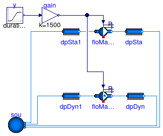
Information
This example demonstrates and tests the use of a flow machine whose mass flow rate is reduced to zero.
The fans have been configured as steady-state models.
This ensures that the actual speed is equal to the input signal.
Extends from Modelica.Icons.Example (Icon for runnable examples), Annex60.Fluid.Movers.Validation.BaseClasses.FlowMachine_ZeroFlow (Base class to test flow machines with zero flow rate).
Parameters
| Type | Name | Default | Description |
|---|
| replaceable package Medium | Air | Medium model |
| MassFlowRate | m_flow_nominal | 1 | Nominal mass flow rate [kg/s] |
| PressureDifference | dp_nominal | 500 | Nominal pressure difference [Pa] |
Modelica definition
model SpeedControlled_Nrpm
extends Modelica.Icons.Example;
extends Annex60.Fluid.Movers.Validation.BaseClasses.FlowMachine_ZeroFlow(
gain(k=1500),
redeclare Annex60.Fluid.Movers.SpeedControlled_Nrpm floMacSta(
redeclare package Medium =
Medium,
per(pressure(V_flow={0,m_flow_nominal,2*m_flow_nominal}/1.2,
dp={2*dp_nominal,dp_nominal,0})),
filteredSpeed=false,
energyDynamics=Modelica.Fluid.Types.Dynamics.SteadyState),
redeclare Annex60.Fluid.Movers.SpeedControlled_Nrpm floMacDyn(
redeclare package Medium =
Medium,
per(pressure(V_flow={0,m_flow_nominal,2*m_flow_nominal}/1.2,
dp={2*dp_nominal,dp_nominal,0})),
filteredSpeed=false,
energyDynamics=Modelica.Fluid.Types.Dynamics.FixedInitial));
equation
connect(gain.y, floMacSta.Nrpm);
connect(gain.y, floMacDyn.Nrpm);
end SpeedControlled_Nrpm;
Fan with zero mass flow rate and control signal y as input
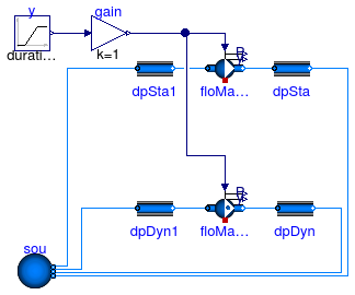
Information
This example demonstrates and tests the use of a flow machine whose mass flow rate is reduced to zero.
The fans have been configured as steady-state models.
This ensures that the actual speed is equal to the input signal.
Extends from Modelica.Icons.Example (Icon for runnable examples), Annex60.Fluid.Movers.Validation.BaseClasses.FlowMachine_ZeroFlow (Base class to test flow machines with zero flow rate).
Parameters
| Type | Name | Default | Description |
|---|
| replaceable package Medium | Air | Medium model |
| MassFlowRate | m_flow_nominal | 1 | Nominal mass flow rate [kg/s] |
| PressureDifference | dp_nominal | 500 | Nominal pressure difference [Pa] |
Modelica definition
model SpeedControlled_y
extends Modelica.Icons.Example;
extends Annex60.Fluid.Movers.Validation.BaseClasses.FlowMachine_ZeroFlow(
gain(k=1),
redeclare Annex60.Fluid.Movers.SpeedControlled_y floMacSta(
redeclare package Medium =
Medium,
per(pressure(V_flow={0,m_flow_nominal,2*m_flow_nominal}/1.2,
dp={2*dp_nominal,dp_nominal,0})),
filteredSpeed=false,
energyDynamics=Modelica.Fluid.Types.Dynamics.SteadyState),
redeclare Annex60.Fluid.Movers.SpeedControlled_y floMacDyn(
redeclare package Medium =
Medium,
per(pressure(V_flow={0,m_flow_nominal,2*m_flow_nominal}/1.2,
dp={2*dp_nominal,dp_nominal,0})),
filteredSpeed=false,
energyDynamics=Modelica.Fluid.Types.Dynamics.FixedInitial));
equation
connect(gain.y, floMacDyn.y);
connect(gain.y, floMacSta.y);
end SpeedControlled_y;
Pump with linear characteristic for pressure vs. flow rate
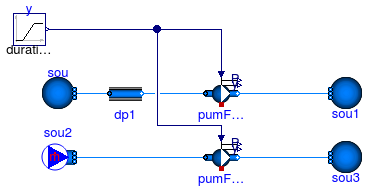
Information
This example demonstrates and tests the use of a flow machine whose speed is reduced to zero.
In the top model, the pressure drop across the pump is constant, and in the bottom model,
the mass flow rate across the pump is constant.
In the top model, a small flow resistance has been added since a pump with zero speed cannot
produce a non-zero pressure raise. For this operating region, the pressure drop ensures that
the model is non-singular.
The fans have been configured as steady-state models.
This ensures that the actual speed is equal to the input signal.
Extends from Modelica.Icons.Example (Icon for runnable examples).
Parameters
Modelica definition
model SpeedControlled_y_linear
extends Modelica.Icons.Example;
package Medium =
Annex60.Media.Water ;
parameter Modelica.SIunits.MassFlowRate m_flow_nominal = 0.5
;
parameter Modelica.SIunits.PressureDifference dp_nominal = 10000
;
Modelica.Blocks.Sources.Ramp y(
offset=1,
duration=0.5,
startTime=0.25,
height=-1) ;
Annex60.Fluid.Sources.Boundary_pT sou(
redeclare package Medium = Medium,
use_p_in=false,
p=300000,
T=293.15,
nPorts=1);
Annex60.Fluid.Movers.SpeedControlled_y pumFixDp(
redeclare package Medium = Medium,
energyDynamics=Modelica.Fluid.Types.Dynamics.SteadyState,
per(pressure(V_flow=2/1000*{0, m_flow_nominal}, dp={2*dp_nominal, 0})),
filteredSpeed=false) ;
Annex60.Fluid.Sources.Boundary_pT sou1(
redeclare package Medium = Medium,
use_p_in=false,
p(displayUnit="Pa") = 300000 + 0.01*dp_nominal,
T=293.15,
nPorts=1);
Annex60.Fluid.FixedResistances.PressureDrop dp1(
redeclare package Medium = Medium,
m_flow_nominal=m_flow_nominal,
dp_nominal=0.01*dp_nominal) ;
Annex60.Fluid.Sources.MassFlowSource_T sou2(
redeclare package Medium = Medium,
nPorts=1,
m_flow=m_flow_nominal*0.01,
T=293.15);
Annex60.Fluid.Movers.SpeedControlled_y pumFixM_flow(
redeclare package Medium = Medium,
energyDynamics=Modelica.Fluid.Types.Dynamics.SteadyState,
per(pressure(V_flow=2/1000*{0, m_flow_nominal}, dp={2*dp_nominal, 0})),
filteredSpeed=false) ;
Annex60.Fluid.Sources.Boundary_pT sou3(
redeclare package Medium = Medium,
use_p_in=false,
p(displayUnit="Pa") = 300000 + 0.01*dp_nominal,
T=293.15,
nPorts=1);
equation
connect(pumFixDp.port_b, sou1.ports[1]);
connect(dp1.port_b, pumFixDp.port_a);
connect(dp1.port_a, sou.ports[1]);
connect(pumFixM_flow.port_b, sou3.ports[1]);
connect(sou2.ports[1], pumFixM_flow.port_a);
connect(y.y, pumFixDp.y);
connect(y.y, pumFixM_flow.y);
end SpeedControlled_y_linear;
http://iea-annex60.org
 Annex60.Fluid.Movers.Validation.ControlledFlowMachine
 Annex60.Fluid.Movers.Validation.PumpCurveConstruction
 Annex60.Fluid.Movers.Validation.PumpCurveDerivatives