| IEA EBC Annex 60 |
|
| IEA EBC Annex 60 |
|
Package with containers to export thermofluid flow models
This package contains containers that can be used, either with replaceable models or through object inheritance, to export HVAC models, HVAC systems and thermal zones. See the Annex60.Fluid.FMI.UsersGuide for instructions.
Extends from Modelica.Icons.Package (Icon for standard packages).
| Name | Description |
|---|---|
| Partial block to export an HVAC system that has no radiative component and that serves multiple zones as an FMU | |
| Partial block to export an HVAC system that has no radiative component and that serves multiple zones as an FMU | |
| Partial block to be used as a container to export a thermofluid flow model with two ports | |
| Container to export thermofluid flow models with two ports as an FMU | |
| Partial block to export a model of a thermal zone as an FMU | |
| Partial block to export a model of multiple thermal zones as an FMU | |
| Collection of models that illustrate model use and test models | |
| Collection of validation models |
 Annex60.Fluid.FMI.ExportContainers.HVACZone
Partial block to export an HVAC system that has no radiative component and that serves multiple zones as an FMU
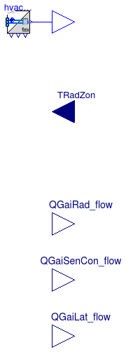
Model that is used as a container for an HVAC system that is to be exported as an FMU and that serves a single zone.
To use this model as a container for an FMU, extend from this model, rather than instantiate it, and add your HVAC system. By extending from this model, the top-level signal connectors on the right stay at the top-level, and hence will be visible at the FMI interface. The example Annex60.Fluid.FMI.ExportContainers.Examples.FMUs.HVACZone shows how a simple HVAC system can be implemented and exported as an FMU. The example Annex60.Fluid.FMI.ExportContainers.Validation.RoomHVAC shows how such an FMU can be connected to a room model that has signal flow.
The conversion between the fluid ports and signal ports is done
in the HVAC adapter hvacAda.
This adapter has a vector of fluid ports called ports.
The supply and return air ducts, including any resistance model for the inlet
diffusor or exhaust grill, need to be connected to these ports.
Also, if a thermal zone has interzonal air exchange or air infiltration,
these flows need to be connected to ports.
This model outputs at the port fluPor the mass flow rate for
each flow that is connected to ports, together with its
temperature, water vapor mass fraction per total mass of the air (not per kg dry
air), and trace substances. These quantities are always as if the flow
enters the room, even if the flow is zero or negative.
If a medium has no moisture, e.g., if Medium.nXi=0, or
if it has no trace substances, e.g., if Medium.nC=0, then
the output signal for these properties are removed.
These quantities are always as if the flow
enters the room, even if the flow is zero or negative.
Thus, a thermal zone model that uses these signals to compute the
heat added by the HVAC system needs to implement an equation such as
Qsen = max(0, ṁsup) cp (Tsup - Tair,zon),
where
Qsen is the sensible heat flow rate added to the thermal zone,
ṁsup is the supply air mass flow rate from
the port fluPor (which is negative if it is an exhaust),
cp is the specific heat capacity at constant pressure,
Tsup is the supply air temperature and
Tair,zon is the zone air temperature.
Note that without the max(·, ·), the energy
balance would be wrong.
The input signals of this model are the zone radiative temperature.
The the zone air temperature,
the water vapor mass fraction per total mass of the air (unless Medium.nXi=0)
and trace substances (unless Medium.nC=0) are obtained from the connector
fluPor.backward.
The outflowing fluid stream(s) at the port ports will be at the
states obtained from fluPor.backward.
All fluid streams at port ports are at the same
pressure.
For convenience, the instance hvacAda also outputs the
properties obtained from fluPor.backward. These can be used
to connect a controller. The properties are available for each flow path in
fluPor.backward. For a thermal zone with mixed air, these are
all equal, while for a stratified room model, they can be different.
See Annex60.Fluid.FMI.ExportContainers.Examples.FMUs.HVACZone for a model that uses this model.
For models that multiple thermal zones connected to the HVAC system, use the model Annex60.Fluid.FMI.ExportContainers.HVACZones.
The mass flow rates at ports sum to zero, hence this
model conserves mass.
This model does not impose any pressure, other than setting the pressure
of all fluid connections to ports to be equal.
The reason is that setting a pressure can lead to non-physical system models,
for example if a mass flow rate is imposed and the HVAC system is connected
to a model that sets a pressure boundary condition such as
Annex60.Fluid.Sources.Outside.
Also, setting a pressure would make it impossible to use multiple instances
of this model (one for each thermal zone) and build in Modelica an airflow network
model with pressure driven mass flow rates.
The model has no pressure drop. Hence, the pressure drop
of an air diffuser or of an exhaust grill needs to be modelled
in models that are connected to ports.
| Type | Name | Default | Description |
|---|---|---|---|
| replaceable package Medium | Modelica.Media.Interfaces.Pa... | Medium in the component | |
| Type | Name | Description |
|---|---|---|
| replaceable package Medium | Medium in the component | |
| Outlet | fluPor[size(hvacAda.fluPor, 1)] | Fluid connector |
| input RealInput | TRadZon | Radiative temperature of the zone [K] |
| output RealOutput | QGaiRad_flow | Radiant heat input into zone (positive if heat gain) [W] |
| output RealOutput | QGaiSenCon_flow | Convective sensible heat input into zone (positive if heat gain) [W] |
| output RealOutput | QGaiLat_flow | Latent heat input into zone (positive if heat gain) [W] |
 Annex60.Fluid.FMI.ExportContainers.HVACZones
Partial block to export an HVAC system that has no radiative component and that serves multiple zones as an FMU
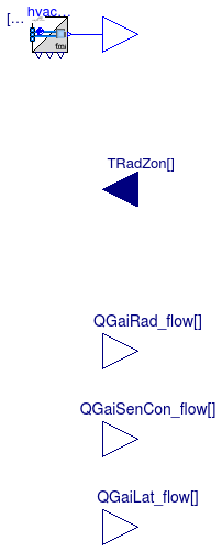
Model that is used as a container for an HVAC system that is to be exported as an FMU and that serves multiple zones.
To use this model as a container for an FMU, simply extend from this model, rather than instantiate it, and add your HVAC system. By extending from this model, the top-level signal connectors on the right stay at the top-level, and hence will be visible at the FMI interface. The example Annex60.Fluid.FMI.ExportContainers.Examples.FMUs.HVACZones shows how a simple HVAC system that serves two rooms can be implemented and exported as an FMU. The example Annex60.Fluid.FMI.ExportContainers.Validation.RoomHVAC shows how such an FMU can be connected to a room model that has signal flow.
The following two parameters need to be assigned by the user:
Set nZon to the number of thermal zones to which the
FMU will be connected.
Set nPorts to the largest number of fluid ports
that the thermal zones has. For example,
if nZon=2 and zone 1 has one inlet and one outlet
(hence it has 2 ports),
and zone 2 has one inlets and two outlets
(hence it has 3 ports), then
set nPorts=3. This will add more fluid ports than are needed
for zone 1, but this causes no overhead if they are not connected.
The conversion between the fluid ports and signal ports is done
in the HVAC adapter hvacAda.
This adapter has a vector of fluid ports called ports.
The supply and return air ducts, including any resistance model for the inlet
diffusor or exhaust grill, need to be connected to these ports.
Also, if a thermal zone has interzonal air exchange or air infiltration,
these flows need to be connected to ports.
This model outputs at the port fluPor the mass flow rate for
each flow that is connected to ports, together with its
temperature, water vapor mass fraction per total mass of the air (not per kg dry
air), and trace substances. These quantities are always as if the flow
enters the room, even if the flow is zero or negative.
If a medium has no moisture, e.g., if Medium.nXi=0, or
if it has no trace substances, e.g., if Medium.nC=0, then
the output signal for these properties are removed.
These quantities are always as if the flow
enters the room, even if the flow is zero or negative.
Thus, a thermal zone model that uses these signals to compute the
heat added by the HVAC system need to implement an equation such as
Qsen = max(0, ṁsup) cp (Tsup - Tair,zon),
where
Qsen is the sensible heat flow rate added to the thermal zone,
ṁsup is the supply air mass flow rate from
the port fluPor (which is negative if it is an exhaust),
cp is the specific heat capacity at constant pressure,
Tsup is the supply air temperature and
Tair,zon is the zone air temperature.
Note that without the max(·, ·), the energy
balance would be wrong.
The input signals of this model are the radiative temperature of each zone.
The the zone air temperatures,
the water vapor mass fractions per total mass of the air (unless Medium.nXi=0)
and trace substances (unless Medium.nC=0) are obtained from the connector
fluPor.backward.
The outflowing fluid stream(s) at the port ports will be at the
states obtained from fluPor.backward.
For any given izon ∈ {1, ..., nzon},
for each iports ∈ {1, ..., nports}
all fluid streams at port ports[izon, iports] are at the same
pressure.
For convenience, the instance hvacAda also outputs the
properties obtained from fluPor.backward. These can be used
to connect a controller. The properties are available for each flow path in
fluPor.backward. For a thermal zone with mixed air, these are
all equal, while for a stratified room model, they can be different.
See Annex60.Fluid.FMI.ExportContainers.Examples.FMUs.HVACZones for a model that uses this model.
For models that only have one thermal zone connected to the HVAC system, use the simpler model Annex60.Fluid.FMI.ExportContainers.HVACZone.
The mass flow rates at ports sum to zero, hence this
model conserves mass for each thermal zone.
This model does not impose any pressure, other than,
for any given izon ∈ {1, ..., nzon} and
for each j,k ∈ {1, ..., nports},
setting the pressure of ports[izon, j].p = ports[izon, k].p
to be the same.
The reason is that setting a pressure can lead to non-physical system models,
for example if a mass flow rate is imposed and the HVAC system is connected
to a model that sets a pressure boundary condition such as
Annex60.Fluid.Sources.Outside.
Also, setting a pressure would make it impossible to use multiple instances
of this model (one for each thermal zone) and build in Modelica an airflow network
model with pressure driven mass flow rates.
The model has no pressure drop. Hence, the pressure drop
of an air diffuser or of an exhaust grill needs to be modelled
in models that are connected to ports.
| Type | Name | Default | Description |
|---|---|---|---|
| replaceable package Medium | Modelica.Media.Interfaces.Pa... | Medium in the component | |
| Integer | nZon | Number of thermal zones served by the HVAC system | |
| Integer | nPorts | Number of fluid ports for each zone (must be the same for every zone) | |
| Type | Name | Description |
|---|---|---|
| replaceable package Medium | Medium in the component | |
| Outlet | fluPor[nZon, nPorts] | Fluid connectors |
| input RealInput | TRadZon[nZon] | Radiative temperature of the zone [K] |
| output RealOutput | QGaiRad_flow[nZon] | Radiant heat input into the zones (positive if heat gain) [W] |
| output RealOutput | QGaiSenCon_flow[nZon] | Convective sensible heat input into the zones (positive if heat gain) [W] |
| output RealOutput | QGaiLat_flow[nZon] | Latent heat input into the zones (positive if heat gain) [W] |
 Annex60.Fluid.FMI.ExportContainers.PartialTwoPort
Partial block to be used as a container to export a thermofluid flow model with two ports

Partial model that can be used to export thermofluid flow models as an FMU. This model only declares the inlet and outlet ports, the medium and whether flow reversal is allowed.
See Annex60.Fluid.FMI.ExportContainers.Examples.FMUs.ResistanceVolume for a block that extends this partial block.
| Type | Name | Default | Description |
|---|---|---|---|
| replaceable package Medium | Modelica.Media.Interfaces.Pa... | Medium in the component | |
| Boolean | use_p_in | true | = true to use a pressure from connector, false to output Medium.p_default |
| Assumptions | |||
| Boolean | allowFlowReversal | true | = true to allow flow reversal, false restricts to design direction (inlet -> outlet) |
| Type | Name | Description |
|---|---|---|
| replaceable package Medium | Medium in the component | |
| Inlet | inlet | Fluid inlet |
| Outlet | outlet | Fluid outlet |
Annex60.Fluid.FMI.ExportContainers.ReplaceableTwoPort
Container to export thermofluid flow models with two ports as an FMU
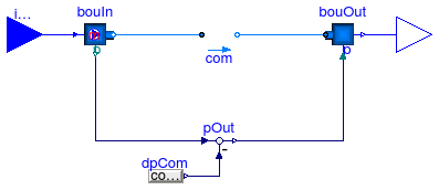
Block that serves as a container to export a thermofluid flow component.
This block contains a replaceable model com that needs to
be redeclared to export any model that has as its base class
Annex60.Fluid.Interfaces.PartialTwoPort.
This allows exporting a large variety of thermofluid flow models
with a simple redeclare.
See for example Annex60.Fluid.FMI.ExportContainers.Examples.FMUs.PressureDrop or Annex60.Fluid.FMI.ExportContainers.Examples.FMUs.HeaterCooler_u for how to use this block.
Note that this block must not be used if the instance com
sets a constant pressure. In such a situation, use
Annex60.Fluid.FMI.ExportContainers.PartialTwoPort
together with
Annex60.Fluid.FMI.InletAdaptor
and
Annex60.Fluid.FMI.OutletAdaptor
and set the pressure to be equal to the port p of
Annex60.Fluid.FMI.OutletAdaptor.
Extends from Annex60.Fluid.FMI.ExportContainers.PartialTwoPort (Partial block to be used as a container to export a thermofluid flow model with two ports).
| Type | Name | Default | Description |
|---|---|---|---|
| replaceable package Medium | PartialMedium | Medium in the component | |
| Boolean | use_p_in | true | = true to use a pressure from connector, false to output Medium.p_default |
| PartialTwoPort | com | redeclare Annex60.Fluid.Inte... | Component that holds the actual model |
| Assumptions | |||
| Boolean | allowFlowReversal | true | = true to allow flow reversal, false restricts to design direction (inlet -> outlet) |
| Type | Name | Description |
|---|---|---|
| Inlet | inlet | Fluid inlet |
| Outlet | outlet | Fluid outlet |
 Annex60.Fluid.FMI.ExportContainers.ThermalZone
Partial block to export a model of a thermal zone as an FMU
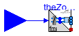
Model that is used as a container for a single thermal zone that is to be exported as an FMU.
To use this model as a container for an FMU, extend from this model, rather than instantiate it, add your thermal zone and a vector of mass flow rate sensors. By extending from this model, the top-level signal connectors on the left stay at the top-level, and hence will be visible at the FMI interface.
Note thatnPorts.
theZonAda and your thermal
zone will be rejected. The reason is because autosized fluid ports
can only be connected to vector of ports whose sizes are literal.
The example Annex60.Fluid.FMI.ExportContainers.Examples.FMUs.ThermalZone shows how a simple thermal zone can be implemented and exported as an FMU. The example Annex60.Fluid.FMI.ExportContainers.Validation.RoomHVAC shows how such an FMU can be connected to an HVAC system that has signal flow.
The conversion between the fluid ports and signal ports is done
in the thermal zone adapter theZonAda.
This adapter has a vector of fluid ports called ports[nPorts]
which needs to be connected to the air volume of the thermal zone.
At this port, air exchanged between the thermal zone, the HVAC system
and any infiltration flow paths.
This model has input signals fluPor[nPorts], which carry
the mass flow rate for each flow that is connected to ports, together with its
temperature, water vapor mass fraction per total mass of the air (not per kg dry
air), and trace substances. These quantities are always as if the flow
enters the room, even if the flow is zero or negative.
If a medium has no moisture, e.g., if Medium.nXi=0, or
if it has no trace substances, e.g., if Medium.nC=0, then
the output signal for these properties are removed.
Thus, a thermal zone model that uses these signals to compute the
heat added by the HVAC system need to implement an equation such as
Qsen = max(0, ṁsup) cp (Tsup - Tair,zon),
where
Qsen is the sensible heat flow rate added to the thermal zone,
ṁsup is the supply air mass flow rate from
the port fluPor (which is negative if it is an exhaust),
cp is the specific heat capacity at constant pressure,
Tsup is the supply air temperature and
Tair,zon is the zone air temperature.
Note that without the max(·, ·), the energy
balance would be wrong.
Models in the package
Annex60.ThermalZones.Detailed
as well as the control volumes in
Annex60.Fluid.MixingVolumes
implement such a max(·, ·) function.
The zone air temperature,
the water vapor mass fraction per total mass of the air (unless Medium.nXi=0)
and trace substances (unless Medium.nC=0)
can be obtained from the outupt connector
fluPor.backward.
These signals are the same as the inflowing fluid stream(s)
at the port theAdaZon.ports[1:nPorts].
The fluid connector ports[nPorts] has a prescribed mass flow rate, but
it does not set any pressure.
This model has a user-defined parameter nPorts
which sets the number of fluid ports, which in turn is used
for the ports fluPor and ports.
All nPorts
ports[1:nPorts] need to be connected as demonstrated in the example
Annex60.Fluid.FMI.ExportContainers.Examples.FMUs.ThermalZone.
The example Annex60.Fluid.FMI.ExportContainers.Validation.RoomHVAC shows conceptually how such an FMU can then be connected to a HVAC system that has signal flow.
| Type | Name | Default | Description |
|---|---|---|---|
| replaceable package Medium | Modelica.Media.Interfaces.Pa... | Medium model | |
| Integer | nPorts | Number of fluid ports | |
| Type | Name | Description |
|---|---|---|
| replaceable package Medium | Medium model | |
| Inlet | fluPor[nPorts] | Fluid connector |
 Annex60.Fluid.FMI.ExportContainers.ThermalZones
Partial block to export a model of multiple thermal zones as an FMU
Model that is used as a container for a multiple thermal zones that are to be exported as an FMU.
To use this model as a container for an FMU, extend from this model, rather than instantiate it, add your thermal zones. For each thermal zone, add a vector of mass flow rate sensors. By extending from this model, the top-level signal connectors on the left stay at the top-level, and hence will be visible at the FMI interface.
Note thatnPorts.
theZonAda and your thermal
zone will be rejected. The reason is because autosized fluid ports
can only be connected to vector of ports whose sizes are literal.
The example Annex60.Fluid.FMI.ExportContainers.Examples.FMUs.ThermalZones shows how multiple simple thermal zones can be implemented and exported as an FMU. The example Annex60.Fluid.FMI.ExportContainers.Validation.RoomHVAC shows how such an FMU can be connected to an HVAC system that has signal flow.
The conversion between the fluid ports and signal ports is done
in the thermal zone adapter theZonAda[nZon].
This adapter has a vector of fluid ports called ports[nPorts]
which needs to be connected to the air volume of the thermal zones.
At this port, air exchanged between the thermal zones, the HVAC system
and any infiltration flow paths.
This model has input signals fluPor[nZon, nPorts] which carry
the mass flow rate for each flow that is connected to ports[1:nPorts]
for the respective zone, together with its
temperature, water vapor mass fraction per total mass of the air (not per kg dry
air), and trace substances. These quantities are always as if the flow
enters the respective room, even if the flow is zero or negative.
If a medium has no moisture, e.g., if Medium.nXi=0, or
if it has no trace substances, e.g., if Medium.nC=0, then
the output signal for these properties are removed.
Thus, a thermal zone model that uses these signals to compute the
heat added by the HVAC system need to implement an equation such as
Qsen = max(0, ṁsup) cp (Tsup - Tair,zon),
where
Qsen is the sensible heat flow rate added to the thermal zone,
ṁsup is the supply air mass flow rate from
the port fluPor (which is negative if it is an exhaust),
cp is the specific heat capacity at constant pressure,
Tsup is the supply air temperature and
Tair,zon is the zone air temperature.
Note that without the max(·, ·), the energy
balance would be wrong.
Models in the package
Annex60.ThermalZones.Detailed
as well as the control volumes in
Annex60.Fluid.MixingVolumes
implement such a max(·, ·) function.
For each zone, its air temperature,
water vapor mass fraction per total mass of the air (unless Medium.nXi=0)
and trace substances (unless Medium.nC=0)
can be obtained from the outupt connector
fluPor[1:nZon].backward.
These signals are the same as the inflowing fluid stream(s)
at the port theAdaZon[1:nZon].ports[1:nPorts].
The fluid connector ports[nPorts] has a prescribed mass flow rate, but
it does not set any pressure.
This model has a user-defined parameter nPorts
which sets the number of fluid ports, which in turn is used
for the ports fluPor and ports.
All zones must have the same number of fluid ports nPorts.
All nPorts
ports[1:nPorts] need to be connected as demonstrated in the example
Annex60.Fluid.FMI.ExportContainers.Examples.FMUs.ThermalZones.
The example Annex60.Fluid.FMI.ExportContainers.Validation.RoomHVAC shows conceptually how such an FMU can then be connected to a HVAC system that has signal flow.
| Type | Name | Default | Description |
|---|---|---|---|
| replaceable package Medium | Modelica.Media.Interfaces.Pa... | Medium model | |
| Integer | nZon | Number of thermal zones in this container | |
| Integer | nPorts | Number of fluid ports for each zone (must be the same for every zone) | |
| Type | Name | Description |
|---|---|---|
| replaceable package Medium | Medium model | |
| Inlet | fluPor[nZon, nPorts] | Fluid connectors |